Important Reminders
- Remember to follow each step and create the code as you go!!
- Refer frequently to the dpeaArduinoStyleGuide.
Setup
- Watch this video on Pulse Width Modulation (PWM), stopping at 0:59 . Note that the electronics will be handled by our Arduino and LED Shield.
- Create a new folder in your Arduino folder named KineticSculpture.
- Create a new sketch and save it in the KineticSculpture folder as YourInitials_rgbTesting.ino
- Copy and paste the starter sketch given here:
/* KS_RGB_Testing - Written by Kyle Stewart and YOUR_NAME - Updated DATE */ //////////////////////////////////////////////////////////////////////////////////////////////////////////////////////// // // // Function Declarations (Verbs) // // // //////////////////////////////////////////////////////////////////////////////////////////////////////////////////////// // Transitioning Functions void setColors(); // Gamma Correction Functions void calculateGammaCorrection(byte rgbArray[]); byte readGammaTable(byte input); // Next Transition Functions void checkIfDataIsIncoming(); void parseStringForNextColor(); void echoInput(); //////////////////////////////////////////////////////////////////////////////////////////////////////////////////////// // // // Global Variable Declarations (Nouns) // // // //////////////////////////////////////////////////////////////////////////////////////////////////////////////////////// //////////////////////////////////////////////////////////////////////////////////////////////////////////////////////// // // // Main Functions // // // //////////////////////////////////////////////////////////////////////////////////////////////////////////////////////// //////////////////////////////////////////////////////////////////////////////////////////////////////////////////////// // // // Transitioning Functions // // // //////////////////////////////////////////////////////////////////////////////////////////////////////////////////////// - Open, read, and refer to the dpeaArduinoStyleGuide. Your architecture should follow the formatting and thought process.
Current Objective: Control the LED strip using the red, green, and blue channels.
Requirements
- Cleanly format your code to maximize organization and readability like the Style Guide (seen above).
- Clarify the purpose of each function and variable through smart naming.
- Use headers and comments as needed to enhance organization.
Turning on the LED Strip
- Congratulations! You've graduated to the Arduino Mega!
- Set the Board Type to Arduino/Genuino Mega or Mega 2560 and the Port to the one that says "(Arduino/Genuino Mega)". These are found in the Tools menu
- Read this resource on enumeration.
- Under the Global Variable Declarations, enumerate the colors red, green, and blue with the statement colors {red, green, blue}; (hint: the answer is the keyword for enumeration).
- Examine the following Kinetic Sculpture Printed Circuit Board (PCB) schematic to determine the pins for the red, green, and blue channels:
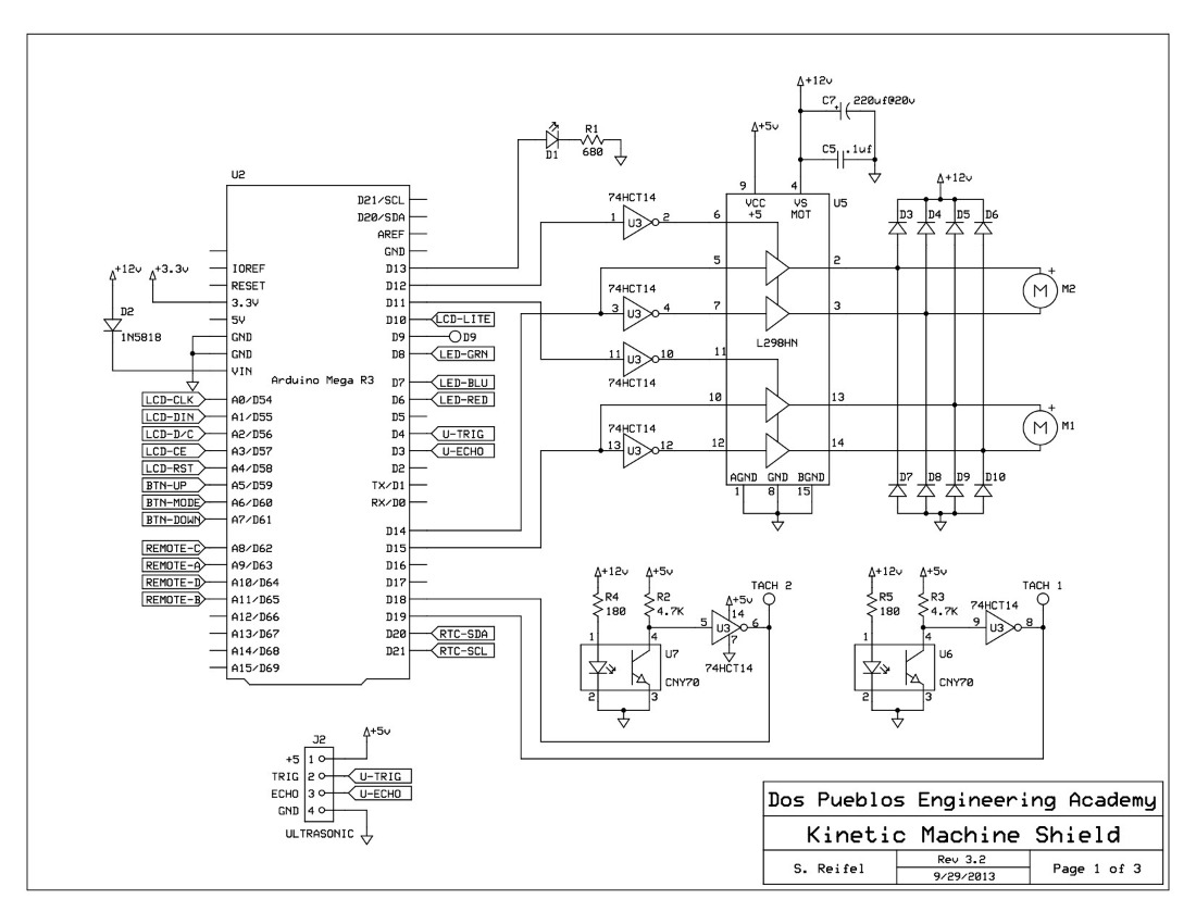
- Declare three global constant byte variables - redPin, greenPin, and bluePin - and assign them values based on the schematic. The redPin declaration statement is . Refer back to the Variables quiz if you need a refresher.
- Declare a global constant byte array named rgbPins with the statement = {redPin, greenPin, bluePin};
- Declare a global byte array rgbValue and initialize each of its elements to 127.
- In the definition of setup, call a function named setColors using the statement (hint: it has no parameters).
- In the section named Transitioning Functions, define the function setColors with the statement (hint: it is a void function).
- Create a for loop in setColors that declares a byte variable color and increments (color++) it from red to blue using the statement (see the dpeaArduinoStyleGuide for formatting).
- Inside of this loop, write each rgbPins[color] with its corresponding rgbValue[color] by calling a built-in Arduino function. Then set the RGB colors by calling the function named . The syntax for this function is similar to digitalWrite(pin, value), where value is between 0 and 255 (one byte).
- Read this resource as a reminder of how PWM works.
- Upload your code and observe the result. Let there be light!
- Experiment with other combinations of rgbValues Try at least three other combinations to see which you prefer.
Did you create all the code for this page?
Before you click the next button, check you followed EACH instruction!!
Back Next Page